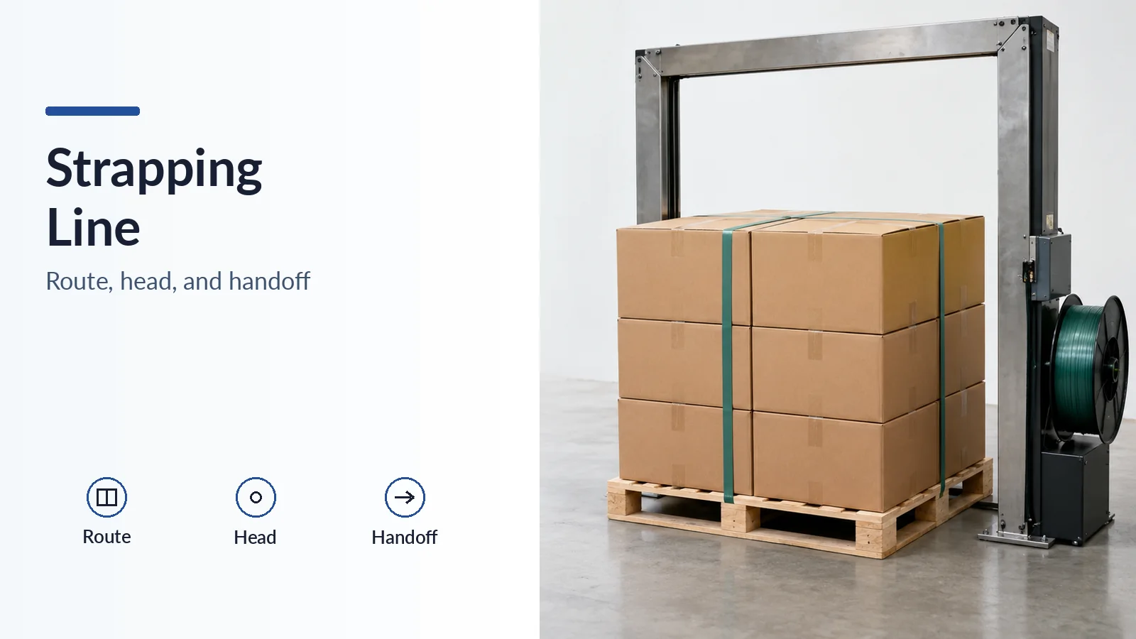
Treating strap width as the line interface loses the information that determines whether a pallet can enter, be secured, and leave a strapping machine. A nominal width match leaves the pallet return path, permitted load envelope, head approval, joint performance, and release conditions unresolved. Specify those together before deciding where the strapper belongs between palletizing and wrapping.
For the upstream build, the case palletizer guide explains how the stack is formed. The handoff here begins with that actual stack and pallet, including their stability before restraint is complete. Related engineering worksheets are collected in the packaging guides.
Define the load and restraint before choosing the sequence
Record the pallet style and void orientation, loaded dimensions and overhang, stacking stability, and intended handling and transport. Identify whether the restraint must contain the cases, connect the product to the pallet, or do both. These are separate requirements to verify on the proposed strap route.
Mosca’s strap-and-wrap guidance describes film as useful for unstable or uneven stacks as well as dust and moisture protection. It describes strapping as providing a product-to-pallet bond for demanding handling. That supports considering both methods where the load needs both functions; it does not establish a fixed share of restraint for either material.
A palletizing, strapping, then wrapping layout is a candidate when the load can remain stable until the strap is applied. A wrapping-first layout needs its own check of film position, head access, pallet openings, and the complete strap path. Evaluate the actual sequence with the least stable production load rather than assuming the final secured pallet represents every transfer state.
Mosca documents direct communication between a pallet strapper and a wrapper in its integration announcement. This establishes an OEM integration example. It supplies neither a universal station order nor a production rate for another cell.
Make transfer and release conditions explicit
Agree on the meaning and owner of each handoff condition. The following are proposed functional states for application review, with their actual signal names and truth conditions to be defined by the integrator:
- Receiving ready: the cell can accept the next pallet under the agreed transfer conditions.
- Positioned and stopped: the load is at the required strapping location and movement has ceased as required by the sequence.
- Securing in progress: the planned strapping operation is incomplete and release remains inhibited.
- Cycle complete and strap applied: the agreed completion evidence is present. Define exactly what the installed indication detects.
- Downstream ready and release authorized: the receiving station can take the load and the cell’s release conditions are satisfied.
- Fault and recovery: the sequence holds and resumes only through the agreed recovery procedure.
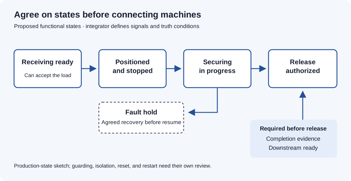
The TSM-3000 brochure lists positioning, conveyor controls, network interfaces, and guarding as options. Their presence in a catalog does not establish the installed interface. Specify the combined cell’s guarding, isolation, reset, and restart behavior separately from its production-state messages; communication alone is not a safety function.
Trace a closed loop through the pallet
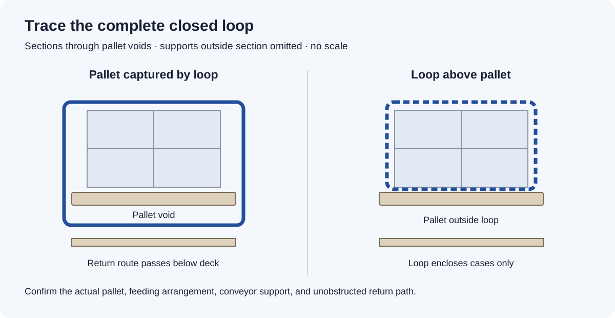
Draw the entire strap route in a section through the loaded pallet. Mark the head, chute, feed and return route, pallet openings, conveyor support, and any obstruction. Identify what the closed loop actually encloses.
A loop wholly above the pallet can surround the cases without enclosing the pallet. This is a geometric distinction: a product-to-pallet tie requires a route that captures the pallet as intended. A visible band on the cases does not establish that connection.
The MH-P brochure lists underfeed and pallet-void feeding options, along with strap-applied and out-of-strap switches. It also distinguishes chute size from maximum package dimensions. Confirm the configured route and package envelope against the actual pallet drawing, including changes in pallet orientation.
Rule of thumb: if the load envelope is outside the configured package envelope, changing PP to PET does not create clearance. Resolve the physical fit and return path on the integration drawing before evaluating material changes.
Approve the strap, head, and joint as a combination
EAM-Mosca describes PP strapping as suitable for lighter palletized loads and identifies PET as a possible choice for heavier or highly compressible loads. Its PET guidance emphasizes tension retention and machine-grade feeding and sealing consistency. These are qualitative selection inputs. They do not define a PP/PET load-weight cutoff or approve a particular coil for another manufacturer’s head.
Check the exact material, width, thickness, surface, coil and dispenser arrangement, head configuration, and production settings together. The TSM-3000 brochure describes friction welding of flat and embossed plastic strap and names PP and PET. Surface finish alone therefore cannot establish a generic welding rule.
A width check that leaves approval open
The Signode TSM-3000 brochure lists a strap size of 9 - 16 mm. Patel’s smooth PET specification includes 10.5 mm × 0.5 mm strap with a declared minimum breaking strength of 2163 N / 221 KGF. The necessary width check is:
9 mm <= 10.5 mm <= 16 mm
The width lies inside the published interval. This does not approve the strap for the machine: the brochure does not establish the supported thickness window, exact grade approval, production weld settings, or resulting joint performance for that Patel strap.
Patel’s declared breaking force describes the strap component. It is neither a finished-joint result nor a pallet rating, and the KGF entry is a force unit, not an allowable pallet mass. Patel states IS:15559 : 2004 and ASTM : D:3950 - 04 as its test methods. These are Patel’s stated older editions; they do not establish compliance with a current standard edition.
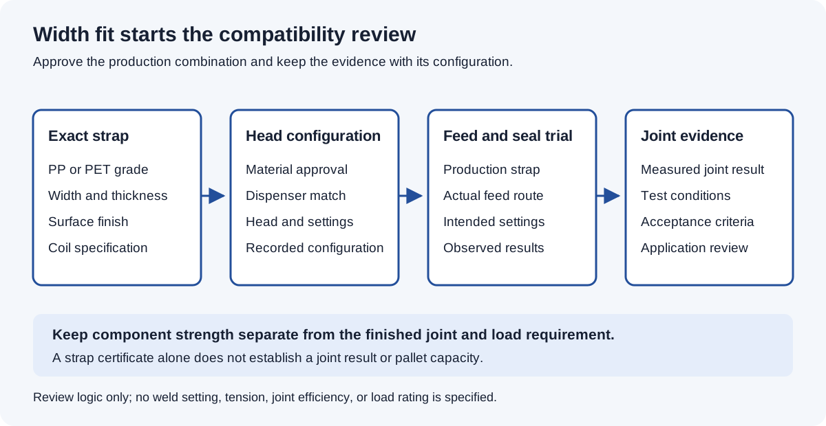
Make and evaluate joints using the actual production strap and intended settings. Keep the joint results distinct from the bare-strap certificate and from the load’s required restraint. None of the catalog values above supplies an allowable working tension, joint efficiency, or selected strap count for the application.
Compare integration decisions by their failure mode
The prevention actions below are engineering checks inferred from the documented hardware and securing functions. They are acceptance questions for the project, rather than completed application tests.
| Decision | Dominant Failure Mode | Prevention |
|---|---|---|
| Strapping before wrapping | The load shifts before its intended restraint is complete | Demonstrate stability through every transfer using the least stable production stack. |
| Wrapping before strapping | Film, head access, or the return route conflicts | Review film position and the complete strap path with the actual pallet and materials. |
| Case containment versus pallet tie | The loop surrounds cases but leaves the pallet outside it | Trace the closed loop and confirm the required underfeed or pallet-void arrangement. |
| Load fit | The actual load exceeds the configured package envelope | Compare the measured loaded envelope with the permitted package dimensions. |
| PP/PET changeover | Nominally matching strap feeds or joins incorrectly | Approve the full strap, dispenser, head, and settings combination and evaluate production joints. |
| Downstream release | The load moves with securing incomplete or no receiving capacity | Define completion evidence, downstream readiness, release permission, and fault recovery. |
| Access and restart | Maintenance access is obstructed or restart is uncoordinated | Review the combined cell’s access, isolation, guarding, reset, and restart behavior. |
Account for cell time using measured cycle intervals
For a sequential cell, use the bookkeeping identity:
T_cell = T_transfer + Σ T_strap_cycles + Σ T_reposition + T_release
Transfer covers movement into the strapping position. The strap-cycle sum covers the planned strapping operations; repositioning covers the intervening movements. Release covers the final handoff. Define the boundaries so no interval is counted twice. The durations are not known, so the cell time is not computed.
Obtain the actual durations for the load and pattern, including relevant production and fault conditions. When operations overlap, use an event timeline to find the elapsed cell time instead of adding overlapping intervals. A strap-feed figure alone cannot establish pallets per hour.
For operating-cost review, collect strap consumed per accepted pallet, failed-joint and rethread waste, coil-change and recipe-change time, planned service, recovery time, and blocked-line time. These are proposed accounting fields. Populate them from the cell’s records before calculating costs or savings.
Close the review with application evidence
The review package should identify the loaded envelope and pallet orientation, the complete strap route, the approved strap/head configuration, joint results, and the agreed transfer-state definitions. Include a sequence showing how the least stable stack remains supported until restraint is complete.
During acceptance, demonstrate the normal handoff, an interrupted securing cycle, unavailable downstream equipment, and the agreed recovery and restart procedure. Record the actual observations against the project’s acceptance criteria. The useful outcome is a cell whose physical route, securing process, and release logic have been checked together.
Record those handoff states in the packaging line integration file for the cell. The closure on the cases is a separate decision, covered in the tape versus hot melt selection guide.