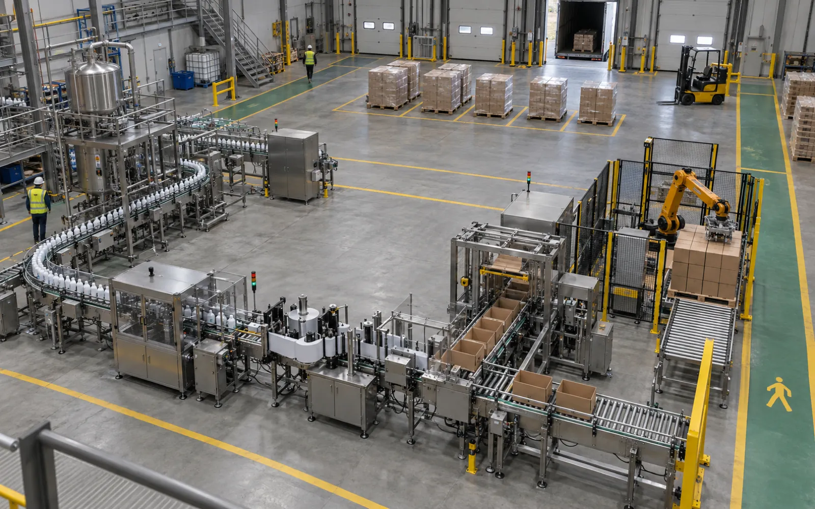
A shape chosen before access and traffic checks can force relocation after installation. Choose among I, L, U and S layouts only after excluding options that conflict with the building, staffing or expansion path. Service and safety envelopes come from the actual machine and site assessment.
| Shape | Main use to check | Exclusion to test |
|---|---|---|
| Straight (I) | Simple through-flow and extension | Building length or cross-traffic access fails |
| L | Corner or docks at right angles | Turn and service access cannot fit |
| U | Nearby ends and shared operator access | Supply crosses working positions or future expansion is blocked |
| Serpentine (S) | Long process in a wider building | Inner-leg access and transfers cannot be maintained |
Before retaining a shape, check building columns, doors and utilities; people access and supply routes; and expansion space. Use the floor-plan inputs and layout worksheet, then its printable clearance checklist. Line design sets rates and buffers; integration assigns the interfaces.
What layout has to decide
Layout answers a small set of questions, and most of them interact:
- Which shape does the line take, and where do its ends sit relative to receiving and shipping?
- Where does material enter, and how does it cross or reach the line?
- Where do operators stand, and what can they see and reach from there?
- What floor space does each machine need for maintenance, changeover, and cleaning?
- How do forklifts, pallet jacks, and pedestrians move around the line?
- Where do power, air, water, drains, and data come from?
- Which areas are hygienic, which are wet, and which are noisy?
- How will the line grow, and what must be left clear?
- Where are the safety boundaries around robots and palletizers?
None of them has a universal numeric answer. Where a value is needed, it comes from the machine manual, the applicable code, or a risk assessment for your site.
Layout shapes
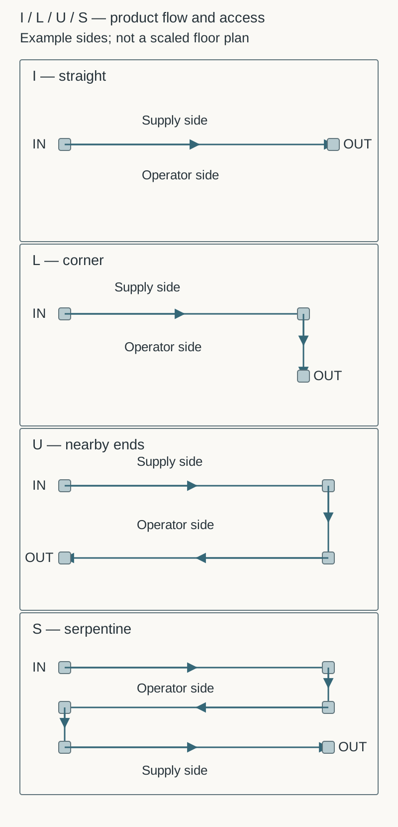
The common line shapes are straight, L, U, and serpentine. They differ less in how the machines run than in how people, material, and building geometry fit around them.
The overview above condenses the I/L/U/S trade-offs. The original lean-manufacturing description emphasizes access on straight lines, operator work inside a U with supply outside, buffers at S turns, and building-driven L layouts. Apply these as qualitative starting points, then check the actual machine envelopes and traffic.
Three practical points follow from that.
Automation shifts the balance. When machines run unattended most of the time, operators visit rather than stay. The reason to put people inside a U weakens, and the reasons to keep the line simple and easy to extend gain weight.
Any shape that places the infeed and discharge at the same end is attractive for plants with one dock, but it puts raw materials and finished goods in the same area. Think about whether those flows will conflict.
Shape is not a style choice. Let the building, column grid, dock positions, and utilities narrow the options first, then compare the remaining shapes against staffing and growth.
Material and people flow
Draw three flows before anything else: product, packaging materials, and people. Product flows from the filler or process through primary packaging, secondary packaging, and palletizing to the dock. Packaging materials such as cartons, film, labels, closures, and pallets flow in the opposite direction, from the warehouse toward the machines that consume them. People move between stations, break areas, and entrances.
The aim is that these flows do not cross at a machine’s working side. Where they must cross, make the crossing deliberate: a single marked point, a bridge, or a gap in the line. A long straight line with no break forces people and material to walk the full length to get to the other side.
Material delivery deserves its own thought. Where do pallets of cartons wait, and who brings them? Where do empty pallets for the palletizer come in? If operators must leave their station to fetch consumables, the layout has hidden labor in it. In a U, material must be brought across or around the line, which requires chutes, conveyors under the line, or a dedicated material handler.
Operator access and sightlines
Each machine has an operating side, a service side, and a place where the operator can see what matters. Plan for all three.
- Place HMIs and controls where the operator can see the machine, the product flow, and the next machine in the sequence.
- Keep the discharge of one machine and the infeed of the next in view of whoever clears jams.
- Check sightlines for supervisors. A U-shaped line lets a lead see more of the process at once. A straight line can match this with a raised position or camera coverage.
- Consider ergonomics: reach to loading points, heights of film and carton magazines, and where changeover parts are kept.
- Provide a safe means of access and egress to every working position. OSHA’s walking-working surfaces rule requires that passageways and work areas be kept clean, orderly, and sanitary, free of hazards such as leaks and spills, and that surfaces support the maximum intended load. A layout that squeezes people between a machine and a wall invites violations of these basics.
The test for any position: can a person get to it, see what they need, and leave quickly if something goes wrong?
Maintenance clearances and service envelopes
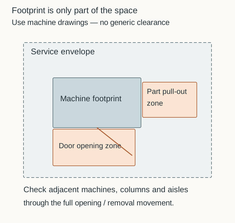
Every machine needs room beyond its footprint. Panels open, guards swing, drives and motors are pulled, rollers and belts are replaced, and film reels or cartons are loaded. This is the service envelope, and it belongs on the floor plan next to the footprint.
Clearance dimensions vary by machine and by what has to move. Use the figures in the machine manual and applicable codes, and check them against your own maintenance practice, including the tools and lifting aids your team will use. Ask each supplier for a drawing that shows the plan, height, and service envelope, and overlay those envelopes on your floor plan. Two envelopes that overlap are a conflict even if the machines themselves do not touch.
Common mistakes include:
- Placing two machines so close that neither side can open fully.
- Forgetting overhead clearance for lifts, spirals, and high-level palletizers.
- Routing conveyors across the one side of a machine that has to open.
- Putting a column or utility drop where a panel swings.
- Leaving no path to bring a replacement motor or gearbox to the machine.
Forklift and pallet paths
Pallets are the heaviest and most disruptive moving object near the line, so plan their routes early. Four pallet flows usually exist: empty pallets in, pallets of packaging materials in, finished pallets out, and rejected or rework pallets.
Follow these principles:
- Separate forklift routes from walkways wherever possible and mark both. OSHA’s general materials handling rule says that wherever mechanical handling equipment operates, aisles, loading docks, doorways, and any place where vehicles turn or pass must have enough safe clearance. It also says aisles and passageways must be kept clear and in good repair, and that permanent aisles must be appropriately marked.
- Give the palletizer and its discharge a direct route to the wrapper and the dock, so finished pallets do not cross the line or an operator station.
- Check the turning needs of the trucks you actually use, including loaded pallets, in aisles and at doors. Dimensions come from the truck specification.
- Provide staging space for incoming pallets of cartons and film near where they are used, without blocking an aisle or a machine’s service side.
- Plan where empty pallets are stored near the palletizer and how they reach the pallet dispenser.
- Post clearance limits for low openings, as the same OSHA rule requires warning signs for clearance limits.
Palletizing systems are the usual destination for these routes. The pallet handling application page covers the wider handling chain.
Utilities routing
Machines need electrical power, compressed air, sometimes water, steam, or vacuum, and drains and data connections. Utilities touch layout in three ways.
- Distance from the source. Long runs cost money and lose pressure or add voltage drop, so keep the utility-heavy machines close to the mains where the line shape allows.
- Routing. Overhead drops, trenches, and floor ducts each have trade-offs. Overhead routes keep floors clear but can conflict with lifts and high-level equipment. Trenches are fixed once poured and are hard to revise.
- Access. Disconnects, regulators, drains, and shutoff valves should be reachable without climbing over a machine or blocking an aisle.
Ask each supplier for the utility connection list and location on the machine. Match them to the available drops on the building drawing, and mark the ones that need new work. Lockout and isolation points should be on a route that a technician can reach quickly, which is another reason to keep aisles clear.
Sanitation zones
Where product is exposed or the area is washed down, layout and hygiene interact. Hygienic zoning means separating areas or processes according to risk, so that the chance of contaminating product is lowered or removed. A common description sorts a plant into zones. A primary pathogen control area, such as a cooked ready-to-eat room, is high risk because product could be re-contaminated before packing. Basic good-practice areas such as receiving and storage are lower risk. Transition areas such as locker rooms, hallways, and entries are generally low risk, and non-production areas such as offices are very low risk.
For layout the consequences are practical:
- Keep the line within the zone it was designed for, and place transitions (hand washing, garment changes, equipment crossings) at zone boundaries.
- Do not route dirty-side traffic, such as pallets and waste, through the clean side of the line.
- Plan drainage so that water does not run from a low-risk area toward a higher-risk one.
- Leave room to wash. If the machine is cleaned in place or by hose, the cleaning crew needs space, drainage, and a way to keep water away from electrical enclosures and the neighboring dry area.
- Separate wet, dry, and dusty processes when you can. Palletizing and shipping often sit in a different zone from filling and primary packaging.
Food, beverage, and similar plants will have written hygiene procedures. Ask sanitation and quality staff to mark the zones on the first draft. The food packaging page covers industry-specific design considerations.
Noise
Noise is easy to forget in a drawing and hard to fix after installation. Case erectors, bottle handling, pneumatic equipment, vibratory feeders, and compressors can all be loud. Where practical, put the loudest machines in a place that is not a main walkway or a break area, and keep control stations and operator positions away from the worst sources. If a station must be near a noisy machine, discuss enclosures, mounting, and hearing protection zones with EHS during the first review. Treat the noise assessment as part of the layout review, not a later check.
Expansion space
Lines grow. A second filler arrives, a faster case packer replaces a slower one, or a new pack format needs an additional station. The cheapest time to prepare for that is the first layout.
- Decide which end or side of the line will grow, and keep that direction free.
- Avoid placing fixed items, such as columns, utility mains, offices, and doors, in the growth path.
- Leave conveyor pass-through gaps where a new machine could be inserted.
- Size electrical and air supply for the likely future load, or at least reserve capacity and space for it.
- Note the growth path on the drawing so a later project does not use the space for something else.
Shapes differ here. A straight line extends easily at either end. A U closes in on itself and is hard to expand, as the same lean-manufacturing source notes. A serpentine can grow by lengthening a leg, but its turns and buffers need to be re-checked.
Safety zoning around robotic cells and palletizers
Palletizers, especially robotic cells, are the part of the line where layout and safety are the same decision. Guarded cells need floor space for the guarding, for the entry points, and for the pallet exchange. The footprint of a cell is larger than the footprint of the machine.
Published sources give two principles. The first is guarding. OSHA’s machine guarding rule requires at least one method of machine guarding that shields the operator and others near the machine from hazards such as the point of operation, ingoing nip points, and rotating parts. Its examples include barrier guards, two-hand tripping devices, and electronic safety devices. A guard should be attached to the machine when that is feasible, and anchored elsewhere when it is not.
The second is restricted space. A summary of the robot safety standard from the Association for Advancing Automation explains that for conventional robot systems the concern has historically been to restrict people’s physical access to hazards. The standard defines the maximum space the moving parts of the robot application can reach, counting the end effector and the workpiece. Limiting access usually means putting fencing around that space, or using safeguards such as a light curtain or pressure-sensitive mat that detects a person and brings the system to a safe stop. The same summary stresses that the system includes the arm, the end effector, the workpiece, and ancillary equipment, so the safety design must consider the whole system, and that a risk assessment is always needed.
In layout terms:
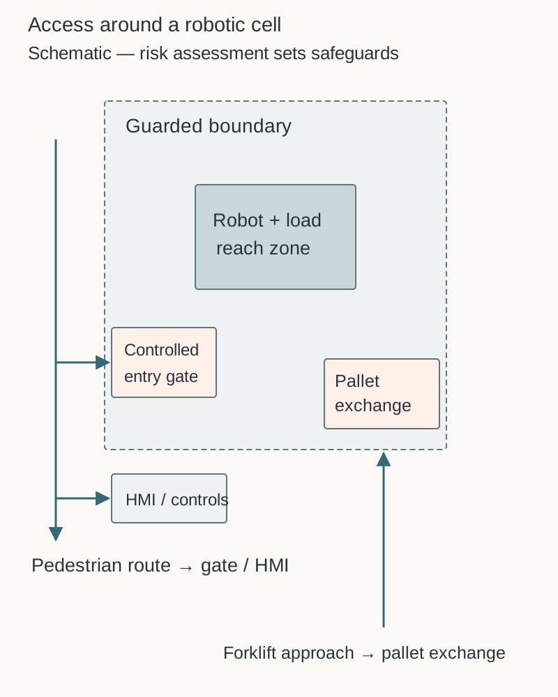
- Show the maximum reach envelope and the guarded boundary on the plan, not just the robot base.
- Position entry doors and pallet exchange points where operators and forklifts can reach them without crossing the line or an infeed conveyor.
- Keep forklift routes out of the guarded area except through controlled openings.
- Place infeed conveyors and discharge conveyors so that the openings in the guarding are as small and as few as the process allows.
- Do not plan on shrinking the guarded area later to fit a smaller space. Let the risk assessment set the boundary, and fit the layout around it.
The robotic palletizers page describes how these cells are put together. Ask suppliers for the reach envelope and guarding layout with each quote, and have EHS review them against your own risk assessment.
Connecting layout to the rest of the line
Layout cannot be settled in isolation. The speed of each machine decides where buffering is needed, and accumulation conveyors take floor space at those points. A turnkey supplier can supply a combined layout across machines, which is covered in turnkey packaging lines. If several suppliers are involved, someone on the project must own the overall drawing.
The how to choose a palletizer guide includes the space questions that change the palletizer selection, which feed back into the layout.
Common layout mistakes
- Starting from machine footprints alone and ignoring service envelopes.
- Choosing a shape because it is fashionable rather than because of the building and staffing.
- Placing the palletizer where trucks cannot reach it.
- Crossing walkways and forklift routes at working positions.
- Leaving no room for a buffer between machines with different rates.
- Forgetting overhead clearance.
- Running utilities to a location that must later move.
- Skipping the reviews: operations, maintenance, EHS, and sanitation each find different problems.
Review before you commit
Layouts improve when the people who will use them review them before steel is ordered. Operations looks at flow, staffing, and sightlines. Maintenance looks at access, spares, and lifting. EHS looks at guarding, aisles, noise, and emergency routes. Sanitation and quality look at zones, drains, and washdown. Use the printable floor-plan review checklist to record those reviews for each drawing revision.
A drawing is cheap to change and a floor is not. Treat the first layout as a hypothesis, test it against the clearances, flows, and zones above, and revise it until each reviewer can walk the line on paper and find no conflicts.