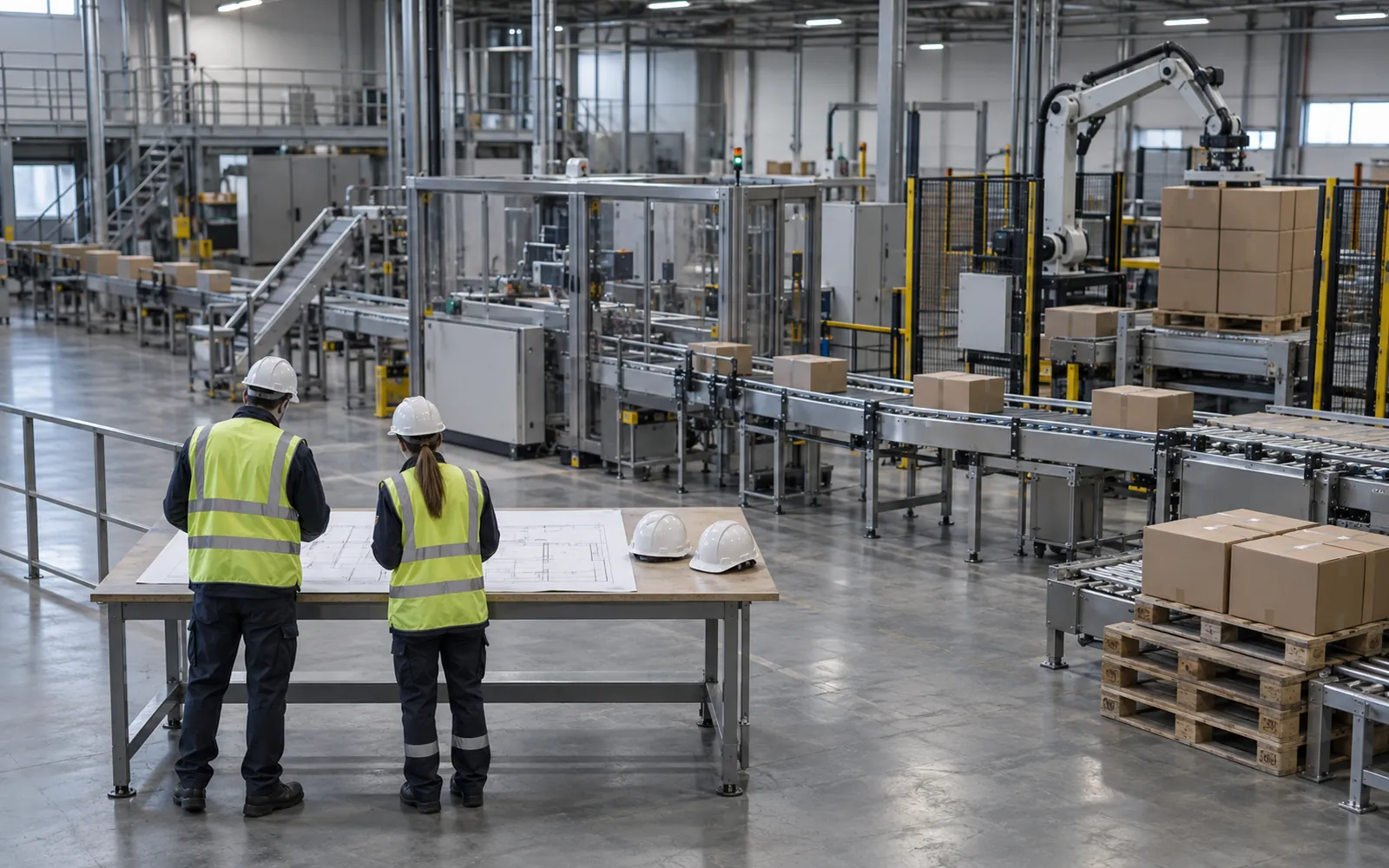
An unscaled floor plan can hide conflicts until installation. Gather the inputs, normalize machine rates, then draw footprints and service envelopes before reviewing clearances. This worksheet applies to new lines, extensions, and rearrangements; use the layout principles for the reasoning.
| Input | Step | Check or output |
|---|---|---|
| Building survey and machine drawings | Gather inputs, draw flow | One scale; columns and service envelopes visible |
| Cases/min, cases/pallet, pallets/hour | Compare rates on one basis | Constraint on the hardest SKU, including pallet exchange |
| Stop time, free buffer positions, pitch in m/case | Place accumulation | Storage and recovery calculation |
| Access, guarding, aisles and utilities | Review and revise | Printable layout checklist |
Step 1: Gather the inputs
A layout drawn from partial information has to be redone. Collect these before drawing.
| Input | What to get | Where it comes from |
|---|---|---|
| Building drawing | Scaled floor plan, ceiling height, floor loading limits, any mezzanines | Facilities, as-built drawings, or a site survey |
| Column grid | Column positions and spacing, including any bracing | Building drawing, confirmed on site |
| Doors and docks | Locations, widths, heights, and what passes through each | Walk the building |
| Utilities | Power, compressed air, water, drains, data, and where each drop is | Facilities and electrical drawings |
| Machine footprints | Length, width, and height for each machine and conveyor | Supplier drawings |
| Service envelopes | The extra floor and overhead space for opening panels, removing parts, loading consumables | Machine manuals and supplier layout drawings |
| Rates | Native rate units, grouping factors, pallet exchange time and effective operating time | Supplier data and your production plan |
| Pallet and forklift routes | Where pallets come in, wait, and leave | Operations and logistics |
| Hygiene zones | Zone boundaries, wet areas, drains | Sanitation and quality |
| Existing equipment | Anything staying, with its footprint and envelope | Walk the building |
Do not accept a footprint without its service envelope. A machine drawn only as a rectangle will be placed too close to its neighbors. If a supplier cannot give an envelope, ask for the manual section on maintenance access.
Verify the building drawing against reality. Columns, pipes, cable trays, and added walls are often missing from drawings. Measure the items that matter most to the layout and note the measuring date.
Step 2: Draw the flow first
Before placing any machines, draw the flow as one line on the plan. Use three colors or line styles:
- Product, from the first machine to the dock.
- Packaging materials and pallets, from storage to the machines that use them.
- People, from entrances and break areas to operator stations.
Start from the real endpoints. Where does the product come from, and where must finished pallets leave? Mark those two points on the building drawing, then draw the shortest sensible path that respects columns, walls, and doors. This sketch will show which line shapes the building allows. Compare it against the shape discussion on the layout principles page and choose the shape the building and staffing favor.
Mark any place where the three flows cross. Each crossing is a decision to make later: remove it, move it, or control it. If the drawing shows too many, the shape or position is wrong.
Step 3: Place the bottleneck machine first
Every line has a machine that limits output. Find it by comparing the rated rate of each machine, adjusted for the real product and format.
- List the machines in flow order with their rates in the same unit.
- Reduce each rate to a realistic sustained rate, using the supplier’s guidance for your hardest product and format.
- The lowest sustained rate is the bottleneck. If two machines are close, treat both as constrained.
Now place that machine first. Give it the best position for its infeed and discharge, its utilities, and its operator access. Then position the others relative to it. Faster machines tolerate adjustments, and the bottleneck does not. If it is squeezed, the line loses output.
Record the choice in a short note on the drawing: machine, rate, why it is the limit, and what would move the limit if a machine were replaced. If the future bottleneck might be a different machine, check that the layout still works with that machine as the constraint.
Step 4: Place the rest of the machines in flow order
With the bottleneck fixed, work outward in both directions along the flow. For each machine:
- Draw its footprint, then its service envelope in a lighter line.
- Connect it to the neighbor with a conveyor and draw the conveyor with its width.
- Check that the operating side faces an aisle.
- Mark its utility connection points and compare them to the available drops.
Put the palletizer and wrapper near the end of the line, close to the dock and to pallet staging. Palletizer choices have layout consequences, such as ceiling height for high-level machines and floor area for guarded robotic cells. Read the how to choose a palletizer guide if the machine type is not settled, because it changes the footprint you draw. For case-level equipment upstream, case packers and case handling explain how the product is grouped and sent forward.
Where the line has to turn or climb, mark the turn, lift, or transfer explicitly. Transfers are where jams and floor space hide. The vertical conveyors page describes how elevation changes are handled.
Step 5: Place accumulation
Accumulation absorbs the difference when machines run at different rates or stop at different times. Place it deliberately rather than leaving leftover floor.
- Mark each junction where a slower or less reliable machine feeds a faster one, and where a downstream machine stops while the upstream one keeps running.
- Record upstream and downstream states during the stop, their rates in the same unit, stop duration in minutes, and free positions at the start. Additional backlog = (upstream rate - downstream rate) × duration; free capacity must cover a positive backlog.
- For a single-lane buffer, multiply required positions by pitch in m/case (case length plus gap) to find occupied path length. Account separately for unusable transfer zones, bends and existing stock.
- Draw that length on the plan. If it does not fit in a straight run, choose a serpentine or looped buffer and draw the full path.
Accumulation conveyors explains the types and how they behave. This worksheet only makes sure the space exists on the drawing. Check the full buffer path on the drawing. After restart, backlog clears only when downstream withdrawal exceeds continuing upstream arrivals; otherwise stop or slow upstream. Recovery time = backlog / positive net withdrawal rate, before allowing for ramp time.
Step 6: Check clearances
Overlay the checks below on the drawing. Mark each one pass or fail in the checklist table in the next section.
- Service envelopes: do any two overlap?
- Aisles: is there a marked aisle at each operating side, and does it reach an exit? OSHA’s materials handling rule calls for sufficient safe clearance for aisles, docks, doorways, and turns where mechanical handling equipment is used, and for permanent aisles to be marked.
- Forklift routes: can each truck reach each pallet position from the aisle, including turns?
- Overhead: do lifts, spirals, and high-level machines clear beams, pipes, lights, and sprinklers?
- Utilities: are drops within reach, and is every disconnect accessible?
- Guarding: for every guarded cell, are the reach envelope, fencing, doors, and pallet exchange openings drawn? OSHA requires machine guarding for hazards such as points of operation and nip points. For robots, the A3 summary describes restricting access to the maximum space the system can reach, typically by fencing or safeguards such as light curtains, with a risk assessment always required.
- Hygiene: do traffic and drains respect the zone boundaries? One hygiene-equipment supplier’s guidance on zoning separates areas to reduce the risk of contamination, with low-risk transition areas, basic areas, and high-risk areas treated differently.
Use values from the machine manuals and applicable codes for every numeric check. The worksheet does not set them.
Step 7: Review with each group
Hold a review with each of four groups. They find different problems, and one meeting with everyone often hides them.
| Group | Questions to ask them | What to record |
|---|---|---|
| Operations | Can operators see and reach what they need? Where do materials wait? Is the flow natural for each shift? | Station positions, material staging, sightline notes |
| Maintenance | Can parts be pulled and replaced? Where do lifting aids go? Are disconnects reachable? | Envelope conflicts, access paths |
| EHS | Are aisles, guarding, emergency exits, noise, and forklift crossings acceptable? | Guarding changes, marked crossings, signage |
| Sanitation and quality | Do zones, drains, and washdown fit? Is anything in the wrong zone? | Zone changes, drain direction, wash access |
Give each group the same drawing and the checklist. Ask them to walk it as if the line were built, from the dock to the palletizer, and mark conflicts in red. Record each comment, who raised it, and the decision.
Step 8: Iterate
Each review yields changes. Apply them, re-run Step 6, and issue a new version with a date and a one-line change note. A typical loop looks like this:
- Version A tests the flow and fit.
- Version B applies envelopes, aisles, and utilities.
- Version C incorporates reviewer comments.
- A final version locks the layout for supplier drawings and floor marking.
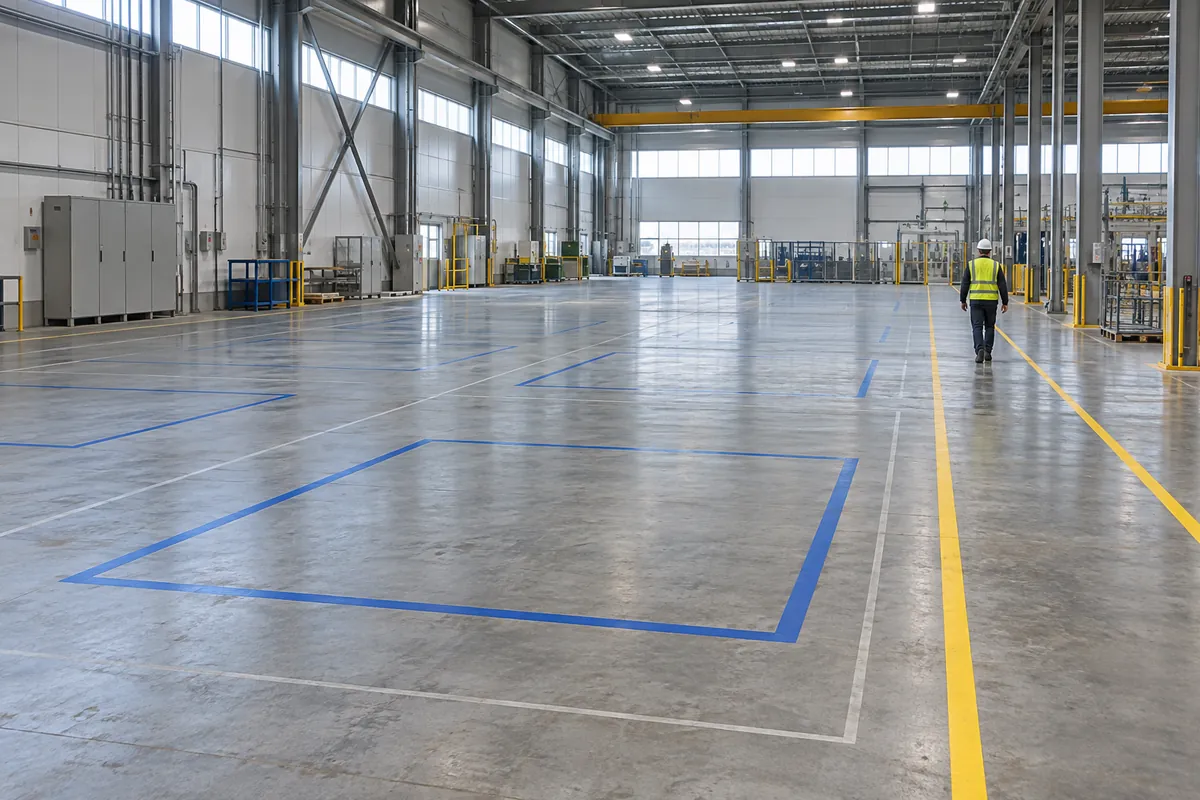
Before locking, do a physical check. Mark machine footprints and envelopes on the floor with tape or chalk and walk the line with operators and maintenance. Anything that feels tight on the floor is tight.
Printable checklist
Print this table for each draft. Mark pass, fail, or not applicable, and note the fix for any failure.
| # | Check | Pass / Fail / N/A | Fix or note |
|---|---|---|---|
| 1 | Drawing is to scale and dated; columns, doors, and utilities verified on site | ||
| 2 | Each machine drawn with footprint and service envelope from supplier data | ||
| 3 | Product, material and pallet, and people flows drawn in separate styles | ||
| 4 | Flow crossings identified and each one controlled or removed | ||
| 5 | Bottleneck machine identified, placed first, and noted on the drawing | ||
| 6 | Each machine’s operating side faces a marked aisle | ||
| 7 | Accumulation drawn at each rate or stop mismatch | ||
| 8 | No overlapping service envelopes | ||
| 9 | Forklift routes reach every pallet position, including turns and doors | ||
| 10 | Overhead clearance confirmed for lifts, spirals, and high-level machines | ||
| 11 | Utility drops reach each machine; disconnects are accessible | ||
| 12 | Guarded cells show reach envelope, fencing, entries, and pallet exchange | ||
| 13 | Hygiene zones, drains, and washdown paths respected | ||
| 14 | Noisy equipment kept clear of walkways and operator stations | ||
| 15 | Growth direction kept free and noted on the drawing | ||
| 16 | Reviews complete with operations, maintenance, EHS, and sanitation | ||
| 17 | Floor walk with taped footprints completed | ||
| 18 | Version number, date, and change note recorded |
Illustrative example
Assumed inputs; a method demonstration, not a scaled layout or a supplier performance claim. This case-handling example has no proven building fit. Do not infer column, service-envelope or aisle clearance from it; those require a dimensioned drawing.
Assume 100 cases per pallet, one format, and rates averaged over the same production window. For the palletizer and wrapper, the listed effective rates already include pallet exchange and an assumed 90% effective operating fraction. Do not apply that fraction again.
| Station | Native effective rate | Grouping | Equivalent cases/min |
|---|---|---|---|
| Case packer | 100 cases/min | No conversion | 100 |
| Case sealer | 120 cases/min | No conversion | 120 |
| Checkweigher | 110 cases/min | No conversion | 110 |
| Palletizer | 140 cases/min | 100 cases/pallet | 140 (84 pallets/hour) |
| Wrapper | 78 pallets/hour | 100 cases/pallet | 78 × 100 / 60 = 130 |
Rate check. The case packer constrains this assumed window at 100 cases/min. Record actual pallet-change duration and operating time for each quoted system before using the same conversion on a project.
Buffer check. Suppose the checkweigher stops for 3 minutes, downstream withdrawal is zero, and upstream continues at 100 cases/min. A buffer with 300 usable positions is initially empty, so all 300 positions are free. Backlog = (100 - 0) × 3 = 300 cases. At an assumed pitch of 0.5 m/case, the storage path alone is 150 m. If 50 positions were already occupied, only 250 would be free and upstream would need to stop before 3 minutes.
Recovery check. After restart, assume immediate withdrawal at 110 cases/min while upstream stays at 100. Net drainage is 10 cases/min, so 300 cases take 30 minutes to clear. Ramp time, a repeated stop, or a downstream limit can lengthen recovery. A downstream rate of 100 cases/min cannot drain the queue while arrivals continue.
Drawing and review. Place the constraint first, then draw the buffer path, machine envelopes, columns and traffic routes to scale. Leave fit unresolved until operations, maintenance and EHS have checked the drawing. Log each revision using the checklist above.
Common mistakes in drafting
- Drawing machines as bare rectangles, with no envelopes.
- Placing the faster machines first and leaving the bottleneck what is left.
- Adding accumulation after the machines are fixed.
- Reviewing only with operations.
- Skipping the floor walk.
- Not recording versions, so decisions cannot be traced.
Where to go next
For the reasoning behind any step, return to the layout principles. To see how floor plans fit into a larger project, read turnkey packaging lines and the packaging line integration hub. Cost implications of conveyor length and turns are in the packaging conveyor cost guide, and beverage lines with similar rate-matching issues are discussed on the beverage packaging page. Supplier drawings should be reviewed against your own checklist before you accept them.